
How to Build a Relaxation Oscillator with a Transistor
In this project, we will show how to build a relaxation oscillator with a single transistor and a few other components such as a resistor and capacitor.
A relaxation oscillator is an oscillator that repeats itself over and over again from the charging of a capacitor to some event threshold and then the discharging of the capacitor.
So basically the repetitive charging up of the capacitor and discharging of the capacitor creates the oscillations in a relaxation oscillator circuit.
The recharge and discharge time of the capacitor determines the time period and, thus, frequency of the signal.
In this circuit, we will connect an LED as output. Since the output signal produces oscillations, you will see that the LED flickers on and off, on and off, indefinitely.
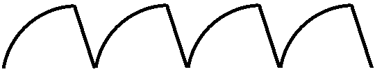
If you have an oscilloscope and you connect the anode of the probe to either to the collector of the transistor or the anode of the capacitor, which are both common, and the cathode to ground, you will see that a sawtooth waveform is generated. A sawtooth wavefrom is one in which the incline of the signal is non-linear. Since a capacitor does not charge up linearly, it does not produce a linear ramp. Instead, a capacitor charges up exponentially according to the formula, V= V0(1 - e-t/T0. So what you'll see is a signal, such as shown above, in which the incline parabolic shaped. A ramp generator is one in which the incline is linear. A sawtooth generator is one in which the incline is nonlinear, or exponential.
In this circuit, with the values we use, the frequency will be rather small, so that you can easily see
the flickering on and off of the LED. But we will show how you can make modifications to the circuit so that you can
change the frequency as well as the amplitude either up or down.
Components Needed
- 2N4401 NPN Transistor
- 3300μF electrolytic capacitor
- 1KΩ resistor
- LED
The 2N4401 transistor is an NPN transistor. The datasheet for this transistor can be found at the following link: 2N4401 NPN Transistor Datasheet.
You really could use any NPN transistor. Other popular transistors are the 2N3904 and 2N2222 NPN transistors.
Relaxation Oscillator Built with a Transistor
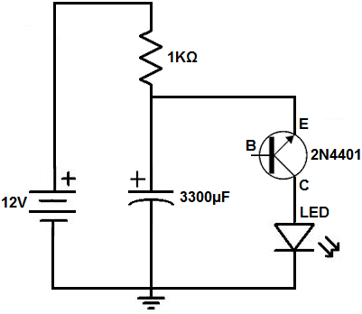
The relaxation oscillator circuit we will build with a transistor and resistor and capacitor is shown below.
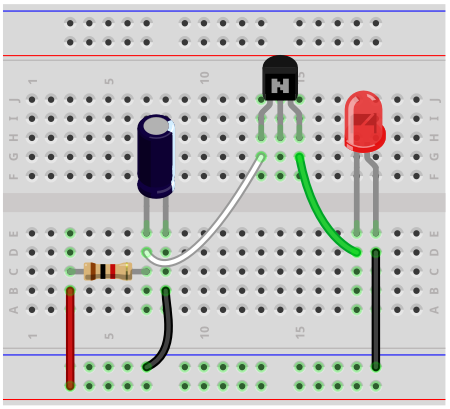
Below is the breadboard schematic version of the above circuit so that you can see the exact wiring of the circuit to the 4011 chip.
First and foremost, we use 12VDC of power for this circuit. Actually any voltage from 12V-15V will work. But voltages much below 12V will not allow the circuit to work.
Next, in parallel to this voltage source, we place a 1KΩ resistor and a 3300μF electrolytic capacitor in parallel. Then in parallel to the capacitor, we place an LED and 2N3904 NPN transistor in series.
We will now explain how this circuit works. So as soon as power is supplied to the circuit, the capacitor charges up through the resistor. It charges up and charges up and charges up. This represents the positive, exponential slope that is present on the first half of the sawtooth waveform. Once the voltage across the capacitor reaches a certain threshold level, the transistor is turned on. Once the transistor is turned on, it can conduct current across from collector to emitter.
So at this voltage threshold, the capacitor stops charging up and begins to discharge. This point represents the peak of the waveform. Once the threshold is reached to turn on the transistor, the capacitor begins to discharge all of its charge. This makes creates current flow from the capacitor, through the LED, and through the transistor. The capacitor Once the capacitor has discharged its current, then the process starts all over again. The current from the power supply charges it up again.
And this creates the infinite sawtooth waveform.
How this circuit works is based on the principle of the transistor being connected reverse biased. The emitter is connected to the anode of the capacitor. The emitter has a relatively low reverse breakdown voltage. If this breakdown voltage is exceeded, then the transistor junction at this region will break down and conduct electricity across from emitter to the collector. This is why we have to use a relatively large voltage of about 12V. If the voltage is too low, say, 5V, for instance, the transistor will not be reached, so that the LED will never light up. If you were to connect the transistor forward biased, with the collector connected to the anode of the capacitor, the circuit will not work at all. The LED will not light up. This is because the collector region has a very large breakdown voltage. In fact, you can go to a transistor's datasheet and see these voltage points. The voltage which we're concerned about in this circuit is the emitter-base voltage. This is when the transistor is reverse biased, when we're apply positive voltage to the emitter of the transistor. Looking at the datasheet for the 2N4401 transistor, it has an emitter-base breakdown voltage of about 6V. This means that if we apply any more than 6V to the emitter, it can cause the transistor region to break down and conduct current. On the other than, the collector-base breakdown voltage is much higher. For the 2N4401, it is 60V. So, for this circuit, we are really taking advantage of the reverse breakdown property of the transistor's emitter-base junction. Once this voltage is exceeded, the transistor conducts current, almost as if a zener diode would once its breakdown voltage is reached.
Another point about this circuit is that the base does not need to be connected in order for the circuit to work. This is because if enough voltage is applied to the emitter junction, the emitter-base junction breaks down and the transistor conducts current. And, of course, the same can be true for a collector if enough voltage was applied to the collector and its breakdown voltage was reached. The transistor would be able to conduct current across without any power directly to the base.
There are several variations that can be done to the circuit.
In order to change the frequency of the circuit, we either the capacitor or the resistor. Since variable resistors, which are potentiometers, are commonplace than variable capacitors, it's easier to use a potentiometer to adjust the frequency of the signal. So if you would like to be able to vary your signal and not just have a fixed signal, then in place of the 1KΩ resistor, you could put a 10KΩ potentiometer. By increasing the resistance, you decrease the frequency. And by decreasing the resistance, you increase the frequency.
If you know the formula, τ= RC, you will know the effect that resistance or capacitance has on the frequency. τ represents the time constant of the signal, which is how long the signal will be. So the time constant represents the time period of a signal, how long each cycle of the signal lasts. So in our case, with a sawtooth waveform, this represents how long one cycle will last, which is one incline and decline. So if the time constant is longer, the frequency will be less. The time period has an inverse relationship with frequency, in which, τ= 1/f. Being that the resistance and capacitance has a direct relationship with the time constant, increasing either one increases the time constant, which decreases the frequency. Decreasing either one decreases the time constant, which increases the frequency. So this is the way to know the effect resistance or capacitance has on the time period and frequency of the cycle.
To change the amplitude, you increase or decrease the supply voltage.
And, of course, you can remove the LED if you simply want the sawtooth waveform. The LED simply stands as a visual way to see the waveform if you don't have an oscilloscope to visualize it. Or you could replace the LED with another output device. Another output device such as a speaker could outplay this sawtooth waveform.
And this is how a relaxation oscillator can be built with a few simple components.
To see how this circuit functions in real life, see the following video below.
Related Resources
How to Build a Clock Circuit with a 555 timer
How to Build an Astable Multivibrator Circuit with Transistors
How to Build a Multivibrator Circuit with a 4047 chip (for astable mode operation)
How to Build a Voltage-Controlled Oscillator Circuit with a 4046 Chip
How to Build an Oscillator Circuit with a 7414 Schmitt Trigger Inverter Chip
How to Build a Sine Wave Generator Circuit with a 555 Timer
How to Build a Ramp Generator with Transistors
How to Build a Voltage-controlled Oscillator with a 555 Timer Chip