How to Build a Voltage Stabilizer Circuit using a Buffer
In this project, we will show how to build a voltage stabilizer circuit using a buffer.
A voltage stabilizer is a circuit that creates and sustains a stable voltage output.
Therefore, the voltage is held stable at that level.
We will show how to keep the voltage that is fed at the input stable at the output, regardless of the load attached to the output.
In this circuit, we will show how to hold a voltage at a stable level regarding of the impedance of the load.
Components Needed
- 4KΩ resistor
- 6KΩ resistor
- LM741 Operational Amplifer Chip
- 270mH inductor
- 470Ω resistor
- LED
So all we need in this circuit is resistors, a buffer chip or an op amp chip, and a load to power on.
In this circuit, we use an LED as a load which requires a current-limiting resistor to limit current to the LED so that it doesn't blow out.
There are 2 ways we can build a voltage stabilizer circuit in terms of chips we can use.
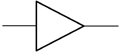
We can use a buffer chip such as the SN7407, which is provide us with buffers directly.
Or we can use an op amp chip such as the LM741 and configure it as a buffer to work with our circuit.
In this circuit, we choose the latter. We will use the LM741 op amp and configure it to be a buffer so that we can get the same function as a buffer in a buffer chip. We will show exactly how an LM741 can be configured to work as a buffer. To see a full article on the pinout for the LM741, see LM741 Op Amp Pinout Connections.
You can also see the datasheet for the LM741 at the following link: LM741 Datasheet.
So these are all the components we need for this circuit.
Now we will discuss the actual circuit itself.
So let's say for a circuit, we have 5V, but we only need 3V out of it to power a load. In other words, our main voltage supply is 5V, yet we only need 3V out of it and not the full 5V.
The easiest way to probably do this is to use a voltage divider. All a voltage divider requires is 2 resistors, making it very easy to break down voltage into any level that we want it (that is below the power supply).
So let's say we have a 5V source but want 3V from it, we can form a voltage divider with 4KΩ and 6KΩ at the bottom. If you were to measure the voltage in between the 2 resistors, it would measure 3V. This is because 5V(6KΩ/4KΩ+6KΩ)= 3V.
So now we have our 3V that we can use. However, if we were to take the 3V, from in between the 2 resistors, and connect it to a load, it would alter the voltage supplied from the 3V.
This bad design is shown below.
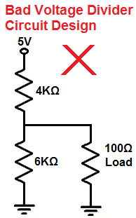
Because the load itself has impedance to it, maybe 100Ω or so, it would alter the 3V, so the 3V wouldn't be stable, so it wouldn't work. This is because a second voltage divider would be created. The first voltage divider is between the 4KΩ and 6KΩ resistor, which creates 3V at the middle of the junction of the resistors. A second voltage divider is then created with the 6KΩ resistor and the load. Because loads typically are 100Ω or so, they are much lower then the resistor in the voltage divider. Being that voltage falls across the greater resistance, according to the formula, V=IR, most of the voltage will fall across the resistor and not the load. Only if the load has a very high resistance or impedance will it obtain most of the voltage created from the voltage divider. However, this is never the case, as many loads are low-impedance devices.
The answer then is to add a buffer to this circuit. Because a buffer has high input impedance and low output impedance, the 3V is maintained. The high impedance at the input makes sure that the voltage is maintained and the low impedance at the output makes sure that the power output at the load is not interfered with too much; because the impedance is low, the load still gets the bulk of the power.
So you can see this circuit connected below.
Voltage Stabilizer Circuit using a Buffer
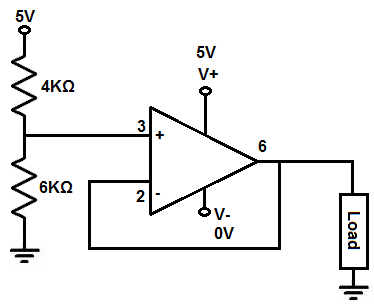
The voltage stabilizer circuit that we will build using a buffer is shown below.
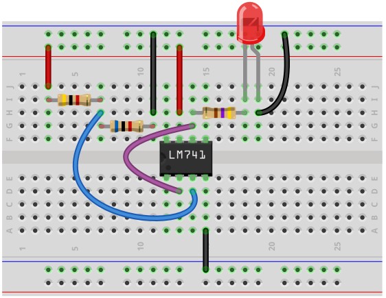
The breadboard circuit of the circuit above is shown below.
So we have our 5V power supply. However, we only want 3V. So we build a voltage divider consisting of a 4KΩ and a 6KΩ resistor. Doing the math, this produces V= 5V (6KΩ/6KΩ+4KΩ)= 3V. So we will have 3V in between the middle of the 2 resistors.
If we were to add a load directly in between the resistors, the 3V wouldn't be maintained because the load has its own impedance, which may be large and weigh down the voltage. This also changes the voltage divider and doesn't guarantee the voltage that it was designed to output.
The better design is to add this voltage from the voltage divider to an op amp. We will use the LM742 operational amplifier in our circuit.
First, to power the LM741, we connect pin 7 to +5V and we connect pin 4 to ground. This establishes sufficient power for the LM741 to be able to operate.
We connect to the voltage from the voltage divider, the 3V, into the noninverting terminal of the LM741, which is pin 3.
We connect the noninverting terminal of the op amp to the output of the op amp, so pin 2 connedts to pin 6 via a jumper wire.
The last pin that we use is the output pin, pin 6. We attach the output device we want to turn on to this output pin. In the breadboard circuit above, we use an LED along with its current-limiting resistor.
When we connect a voltage directly to the noninverting terminal and have the inverting terminal wired directly to ground, the op amp the op amp acts as a buffer. Acting as a buffer, the op amp preserves the voltage from the voltage divider and allows for enough power to turn on the output.
With a high input impedance, all the voltage from the voltage divider falls across the input of the op amp. This is because voltage, V IR, where I is he current and R is the resistance. Being that the resistance, or impedance, is high across the input of the op amp, practically all of from the voltage divider falls across it. So, we're able to keep or preserve all of the voltage from the voltage divider.
With a low output impedance, the power isn't dragged down, so a load can still be powered. If an op amp had high output impedance, it would drag down the power to such a level that current flow would be so low it couldn't power on a device. Current, I=V/R, where V is the voltage and R is the resistance. Being that current is inversely proportional to resistance, or impedance, the higher the impedance, the lower the current. For this reason, the impedance at the output must be low.
And this is how a buffer chip or an op amp acting as a buffer chip works to act as a voltage stabilizer.
Related Resources
How to Build a Square-to-Triangle Wave Converter Circuit
How to Build a Square-to-Sine Wave Converter Circuit
How to Build a Clock Circuit with a 555 timer
How to Build an Astable Multivibrator Circuit with Transistors
How to Build a Multivibrator Circuit with a 4047 chip (for astable mode operation)
How to Build a Voltage-Controlled Oscillator Circuit with a 4046 Chip
How to Build an Oscillator Circuit with a 7414 Schmitt Trigger Inverter Chip
How to Build a Sine Wave Generator Circuit with a 555 Timer
How to Build a Ramp Generator with Transistors
How to Build a Voltage-controlled Oscillator with a 555 Timer Chip