
How to Build a Square-to-Triangle Wave Converter
In this project, we will show how to build a square wave to triangle wave converter.
To do so, we simply need resistors and capacitors- nothing else. Using RC networks, we can reshape a square wave into a triangular wave.
A circuit is like this can be very important because square waves are commonplace in electronics. Many types of digital devices output square waves. Triangle waves are not as commonplace. Even though triangle waves are used much less frequently, in certain cases such as acoustics, they may be needed. Therefore, it's good to know how to convert a square wave to a triangle wave. And this can be accomplished rather easily with just resistors and capacitors.
In fact, to build this circuit, we only need 2 RC networks. Each RC network is comprised of 1 resistor and 1 capacitor. So a total of 2 resistors and 2 capacitors are needed for this circuit.
Even though this circuit is very basic in that it only requires 2 resistors and 2 capacitors, it does contain some complexity in regard to the values of the resistors and more importantly the capacitors in regard to the frequency of the input signal.
The capacitor values that we choose for the circuit is based off the frequency of the input square wave signal. If the capacitor value isn't appropriate for the frequency of the square wave signal, the circuit will not work. So capacitor values must be chosen. If not, the same square wave signal that we feed into the circuit will be output, meaning the capacitors had no effect on the signal because the value of them are out of the frequency range. We will go over the frequency of the signal and the capacitor values needed in more detail below.
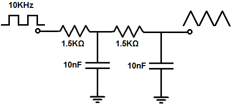
For this circuit, we will input a 50KHz signal. So this circuit, with the given value capacitors given below,
will work square wave signals at or above 10KHz.
Components Needed
- 2 1.5KΩ resistors
- 2 10nF ceramic capacitors
All we need to build this circuit is a square waveform and a few resistors and capacitors.
The square waveform can be generated from a number of sources, including a function generator or a circuit that can produce square waves such as
this 555 timer clock circuit.
Square-to-Triangle Wave Converter Circuit
The square-to-triangle wave generator circuit that we will build with only resistors and capacitors is shown below.
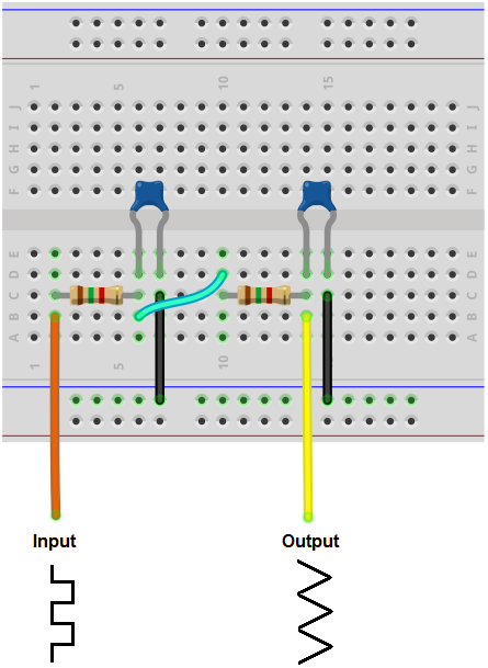
The breadboard circuit of the circuit above is shown below.
So our input signal to the circuit is a square wave.
We then have our first RC network, composed of a resistor and capacitor. The first resistor and capacitor creates the classic capacitor charging and discharging waveform. Being that the voltage across the capacitor, VC= VIN(1 - e-t/RC), the voltage across the capacitor charges up exponentially and discharges exponentially. Therefore, the waveform, upon charging is a parabolic-shaped exponential waveform upside down. The same way the capacitor charges up exponentially, it discharges exponentially. Therefore, when the capacitor is discharging, you see a parabolic-shaped exponential waveform right side up. So this is the waveform that you will see after the first RC network.
After the first RC network, we then have our second RC network. This RC network takes the exponential waveform and converts it into a triangle waveform. It straightens out the parabolic exponential waveforms so that they appear as a straight ascending slope on the charging side and straight descending slope on the discharging side. The result is a triangle.
Just like with the first capacitor, the second capacitor charges and discharges, charges and discharges, over and over again. The result is continous never-ending oscillations of triangle waveforms.
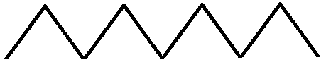
And this is all that is needed to convert square waves into triangle waves.
Now regarding adjustments or modifications that can be made into the circuit; this includes changing the frequency of the waveform and/or the amplitude.
So, as stated above, changing the frequency of the input waveform, which in turn, changes the frequency of the output triangle waveform can be a sticky thing. Different-value capacitors respond to different frequencies, so what capacitors may work for one frequency may not work for another frequency. If you do not choose the right value capacitor for the frequency used, the circuit will not work. It flat out will not work. Depending on what frequency you use, the values of the capacitors needed to be carefully chosen.
For this circuit, the 50KHz frequency and frequency values close to this work very well with the values given above, which are 1.5KΩ resistors and 10nF capacitors.
However, if you vary greatly from this frequency, like by a few KHz and especially as you vary farther than this, the capacitor values will most likely need to be changed in order to produce triangle waveforms as output.
If the correct values are not chosen and are way out of the frequency range, the output waveform will be the same exact square wave, as is input into the circuit, except attenuated a bit due to the resistors. The waveform will be unchanged because the capacitors have no reactance to the voltage due to the frequency level. If the capacitor still has some on the signal due to frequency but is still out of range, you may get a very poorly formed triangle waveform. Therefore, it's very important to choose correct levels.
If you're willing to play around with values, you will know that the capacitors work for the given frequency if you see a triangle waveform from the second capacitor. If you do not, then you can be sure that the capacitor values need to be changed. If the output waveform is a perfect square wave, then you can be sure that the capacitor values are completely out of range for the frequency of the signal. If you see a poorly formed triangle wave, the capacitor value is slightly out of range. Either adjust its value or the frequency.
When swapping out the capacitor values, change both capacitors value at once. You want to use the same value capacitors for both capacitors. This is because if one capacitor works at that frequency, the other will also work at that frequency. If you choose different value capacitors, then one capacitor may work with that frequency, while the other may not. So, in the end, you may get a mixed, poorly defined waveform. To alleviate this problem, use the same value for both capacitors.
The rule of thumb for choosing capacitors is that for low frequencies, higher value capacitors are needed. For high frequencies, lower value capacitors are needed. So for really high frequencies, you may use capacitors in the order of picofarads. For really low frequencies, you may use hundreds of nanofarads, or even units of microfarads. This may require some trial and error and testing with building the circuit and checking the waveform on an oscilloscope.
As far as adjusting the amplitude, this just requires feeding a larger square wave into the circuit to increase the amplitude. Or feeding a smaller square wave into the circuit to decrease the amplitude.
And this is about all that can be done for building and adjusting this square-to-triangle wave converter circuit.
And this is how a sine wave generator circuit can be built with a few simple components.
To see how this circuit works in real life, please see the video below.
Related Resources
How to Build a Square-to-Sine Wave Converter Circuit
How to Build a Triangle to Sine Wave Converter Circuit
How to Build an Adjustable Square Wave Generator Circuit with a
555 Timer
How to Build a Sine Wave Generator Ciruit with a Single Transistor
How to Build a Sine Wave Generator Circuit with a 555 Timer
How to Build a Triangle Wave Generator Circuit with a 555 Timer
How to Build a Clock Circuit with a 555 timer
How to Build an Astable Multivibrator Circuit with Transistors
How to Build a Multivibrator Circuit with a 4047 chip (for astable mode operation)
How to Build a Voltage-Controlled Oscillator Circuit with a 4046 Chip
How to Build an Oscillator Circuit with a 7414 Schmitt Trigger Inverter Chip
How to Build a Ramp Generator with Transistors
How to Build a Voltage-controlled Oscillator with a 555 Timer Chip