
How to Build a DC-to-DC Boost Converter Circuit

In this project, we will show how to build a DC-to-DC boost converter circuit that allows us to manually control the circuit with a pushbutton.
A DC-to-DC boost converter circuit is a circuit that can convert a DC voltage into a larger DC voltage.
So, for example, you may be able to convert a 5V DC voltage into 30V.
A DC-to-DC converter works on the principle of an inductor primarily and a capacitor. When fed DC power, the inductor acts as a energy storage device for current. As long as DC power is supplied to it, it builds up current through the coils as well as a magnetic field around itself. When the DC power is turned off, the magnetic field collapses and all the current that the inductor charged up gets dumped across to the capacitor. As the DC power gets turned on and off in the circuit, which we will do through a pushbutton switch, the inductor stores up more current and dumps it across the capacitor each time. This is why the voltage across the capacitor increases each time we do this until it reaches its peak.
The amount of voltage that the output will increase to depends upon a number of factors including the value of the inductor, the maximum voltage storage of the capacitor, the switching speed, and the DC input voltage of the circuit.
We won't go to in depth mathematically about each relationship but will show how this variables relate to the amount of voltage increase there will be.
In this circuit, we will use a manual pushbutton to switch the DC value on and off.
In a more advanced, real-life circuit, you would use a transistor instead of a manual switch, as this gives more precision and control over the circuit. Unlike manual control, a transistor can switch on and off much quicker, in the order of microseconds, and give much more precision. A microcontroller would control the transistor and it could be coded to turn the transistor on and off at set intervals. Under such control, the output voltage would be able to calculated precisely and the code could be written so that these bursts of DC voltage occurred at desired times.
However, for this circuit, we are simply demonstrating how a DC-to-DC boost converter works and using a pushbutton will do the job
just fine for this circuit.
Components Needed
- 1K?O resistor
- Diode
- Pushbutton switch
- 100mH inductor
- 10µF electrolytic capacitor
So for this circuit, we will use basic discrete components.
This includes a resistor, an inductor, an electrolytic capacitor, and a diode.
In this circuit, we will use a 100mH inductor. Increasing the inductance allows for greater voltage output, because the greater the inductance, the more energy it can store. So if you swap out the inductor for a lower value, it will be able to produce less output voltage. If you swap out the inductor for a higher value, it will be able to put out a higher voltage. So you can play around with inductance values to see how it affects the output voltage. If you do use a higher inductance, it will resist current flow through it since it's a greater value, so the charge up process may take longer, but in the end it produces a higher voltage output.
The electrolytic capacitor should have a voltage rating of about 50V or higher. The higher the rating, the better, because the more voltage it will be able to handle. You do not want the voltage across the capacitor to exceed its voltage rating or it may explode. Being that the boost converter circuit can produce tremendously high voltage, you want as high a rating as you can get, at least definitely well over the 25V rating, which is common with capacitors. You want at least 50V.
You also want the capacitor to be of a fairly high value. This is why we're not using pico or nanofarads for the capacitor but at least 1 microfarad. Since the inductor is putting out large amounts of current, we want the capacitor to have enough capacitance to be able to store this charge.
The diode can really be any diode. We use a 1N4001 diode just because it's easy to find and readily avaiable, even though it isn't the best choice because it uses about 0.7V of voltage drop across it. Take into account, though, that whatever diode you use will produce a voltage drop across the diode. Some diodes use more voltage drop than others, so, ideally, you want to use a diode that has a low voltage drop for as little voltage consumption as possible. This would be for real-life situations where you want as much efficiency in possible in terms of possible voltage output. However, for this circuit, you may not care about the less than 1V lost across the diode. But, just so that you know, the diode will consume some of the output voltage current, making it lower than it would be if you used a less power-consuming diode.
The diode is used in this circuit to provide resistance so that when the pushbutton is pressed, all the current flows from the inductor to ground, creating a short circuit. This is so that the inductor alone gets charged up at this time. When the pushbutton is released, an open circuit is formed at the pushbutton junction, so that all the current then gets discharged through the diode and to the capacitor.
The resistor isn't really necessary for this circuit. It simply acts as the load for the circuit. If you have an actual load that you
want powered on, you could replace the resistor for it. Being that the resistor is in parallel to the capacitor, the voltage across the resistor is
the same as the voltage across the capacitor, because voltage in parallel is equal.
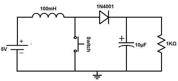
Boost Converter Circuit
The boost converter circuit is shown below.
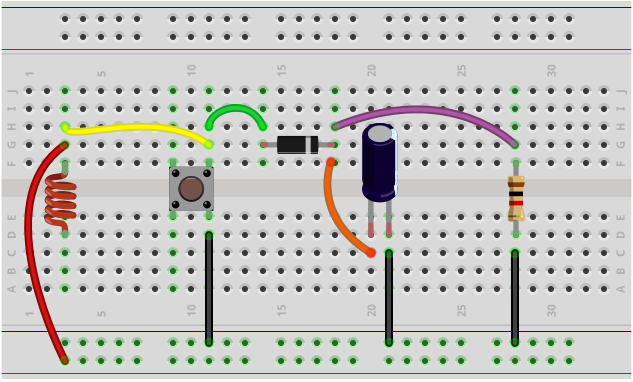
The breadboard circuit of the circuit above is shown below.
So we have 5V as the DC power powering this circuit.
If you were to measure the voltage now across the resistor, it would be about 4.3V, less than the 5V supplied because of the voltage drop across the diode.
Now to increase the output voltage, we press on the pushbutton several times.
You don't want to press on the pushbutton and hold it long at all, less than a second. This is because when you press on the pushbutton, all of the current flows across the inductor and then down to ground, basically creating a short circuit for the inductor. Inductors do not like large amounts of current going through it alone for long. It could fry the inductor. This is why you want to press the pushbutton and release it, press it and release it. This allows for an even distribution of current buildup in the inductor and release to the capacitor. It charges up in increments, not all at once.
So, again, you press the pushbutton several times, charging up the capacitor gradually. Since a capacitor charges logarithmically, you will see a logarithmic increase in voltage over time, such as the waveform shown above.
As you continue pressing the pushbutton, you will see that it begins to peak out a little above 20V.
How this circuit works is that when you press down on the pushbutton, current flow is created through the inductor down to ground via the pushbutton. At this point, all the current flows through the inductor to ground, the lowest path of resistance. No current flows across the diode. This charges up the inductor. The inductor acts as an energy storage device for the current. The greater the inductance, the more energy it is able to store. So the inductor charges up.
Once the pushbutton is released, the junction at the pushbutton becomes an open circuit, so no more current can flow through this junction. The inductor discharges all the current built up on it and dumps it through the diode and to the capacitor, charging up the capacitor. This is when the voltage across the capacitor starts building up. As we keep pressing and releasing the pushbutton, the charge continues to increase, building up the voltage further. This happens until the voltage peaks off.
The voltage peak is determined by a number of factors including the input voltage, the inductance of the inductor, the type of diode being used, the capacitance of the capacitor, and the voltage rating of the capacitor. To increase the voltage output, we would have to increase each factor listed, with the exception of the voltage drop across the diode, which we would want to be as low as possible.
Regarding the input that we want to the inductor, in an actual real-life circuit, we want pulses, such as a pulse width modulated signal to go to the inductor. This is a square wave with a certain duty cycle that turns on and off, on and off, at determined intervals. We never want to feed the inductor a constant current, because this would make it fry. So if you were to build this circuit for real-life, industrial use, we would not be using manual control but set up a circuit to deliver pulse width modulated signals to it. This would allow the inductor to charge up and discharge, charge up and discharge, without the inductor receiving so much current that it would be destroyed. So this illustrates the point why we want to press it and release the pushbutton within a second or less to mimic a square waveform. Again, in real life, this circuit would not be controlled manually by a pushbutton but with a transistor and not with a constant DC power supply but a pulse width modulated signal. But this circuit is just to demonstrate manually how a DC-to-DC boost converter circuit operates.
There are several variations that we can do to this circuit to produce drastic differences in terms of the voltage output.
The biggest change we can make to the circuit to produce drastically different results at the output is to replace the inductor with another component.
The inductor can be replaced with the coil of a relay. This will up the voltage a little over the inductor.
The inductor can also be replaced with a step-up tranformer. If using the primary coil, the voltage can be boosted as high as over
60VDC. If using the secondary coil of the transformer, the voltage can be boosted over 120VDC. The secondary coil is larger coil, which has a greater
inductance, allowing for increased voltage at the output. Know that when you are using a step-up transformer instead of the inductor, the capacitor
should have a voltage rating of 200V or greater. If less than this, the capacitor can be destroyed, as these are very high voltages.
And this is how a DC-to-DC boost converter circuit can be built.
Related Resources
How to Build a Square-to-Triangle Wave Converter Circuit
How to Build a Square-to-Sine Wave Converter Circuit
How to Build a Clock Circuit with a 555 timer
How to Build an Astable Multivibrator Circuit with Transistors
How to Build a Multivibrator Circuit with a 4047 chip (for astable mode operation)
How to Build a Voltage-Controlled Oscillator Circuit with a 4046 Chip
How to Build an Oscillator Circuit with a 7414 Schmitt Trigger Inverter Chip
How to Build a Sine Wave Generator Circuit with a 555 Timer
How to Build a Ramp Generator with Transistors
How to Build a Voltage-controlled Oscillator with a 555 Timer Chip