
How to Build a Dual Polarity Power Supply Circuit
In this project, we will show how to build a dual polarity power supply circuit with a DC power supply.
In this circuit, we are not building a power supply from scratch. We're using an exisiting power supply and showing how to obtain dual polarity from it so that we can supply positive and negative voltage to a circuit.
This is often needed in the case of op amps, many of which are dual supply op amps. In order for these op amps to be able to swing positive and negative, there must be positive and negative rails, which are established by positive and negative voltage supplies.
Thus, it's very important to be able to know how to supply positive and negative voltage from a power supply properly.
Below we'll discuss how to do so.
Components Needed
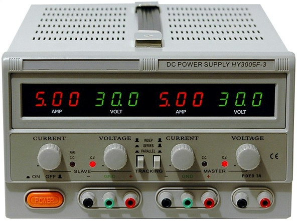
- DC Power Supply
- Jumper Wires
So we can really any DC power supply as long as it has 3 terminals: +, GND, -.
The vast majority of power supplies, even basic ones, come with 3 terminals. So this is really the only requirement.
Other than the power supply itself, we need some jumper wires for connecting the circuit. You should probably have a breadboard
to do this.
Dual Polarity Power Supply
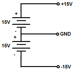
The dual polarity power supply circuit that we will build with an existing DC power supply is shown below.
The breadboard circuit of the circuit above is shown below.
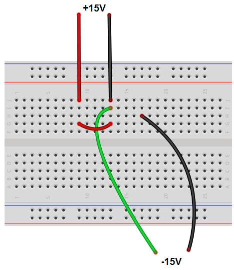
So the circuit that is shown above is all the wires coming from the DC power supply.
On a typical DC power supply, there are 3 terminals for one power supply. These terminals are the positive terminal, ground, and the negative terminal. The 3 terminals are completely separate. Normally the terminals are color-coded. The red terminal is the positive voltage terminal. The green terminal is earth ground. And the black terminal is the negative voltage terminal.
In order to get positive voltage, we connect one end to the positive terminal and connect the other end to the negative voltage terminal which is connected to ground. This creates positive voltage.
In order to get negative voltage, we connect one end to the negative terminal and connect the other to the positive voltage terminal which is connected to ground. This creates negative voltage.
So if we're connecting the positive voltage to the positive rail of an op amp, the red wire goes to that terminal.
If we're connecting negative voltage to the negative rail of an op amp, the black wire goes to that terminal.
Both the positive and the negative voltage share grounds, so both grounds are common.
This circuit, more than anything, shows how to properly use a DC power supply to provide either or both positive and negative voltages.
Realize that the 3 terminals of a power supply allow this is to easily happen. Either the red terminal is connected to the negative terminal which is connected to earth ground (green) which creates positive voltage or the negative terminal is connected to the positive terminal which is connected to earth ground (green), which creates negative voltage.
Many times, when negative voltage is not used, as is the case with most circuits, engineers will tie both the negative and ground terminals together such as through a small jumper wire. This way, an engineer the negative voltage is tied to earth ground. This is normally how it would be if you're only using positive voltage. If they are not tied together, this would represent a floating ground, because the negative terminal is not connected to true ground, which is earth ground. This is why it is described as a floating ground, being that is not connected to earth. To create a true ground, engineers will always connect the negative terminal to earth ground to create a true ground for the circuit.
Anyways, back to the point of dual polarity power supplies, the greatest application is for op amps, which many times deal with AC signals, which alternate from positive to ground and then swings negative. In order to create positive and negative rails, the op amp needs DC power biased at a positive voltage reference level and a negative voltage reference level. So if we supply an op amp with +15V and -15V, the AC signal passing through can swing up and down to these levels.
If we simply connect the V+ terminal to positive voltage and the V- terminal to ground, an AC signal will clip at the ground mark and not swing below it. Thus, it would be unsuitable for AC signal applications. This is why both positive and negative voltages are needed. The only other alternative with a single supply op amp for it to function well with AC signals is to provide DC offset to the AC signal so that it doesn't the bottom half of the signal does not get clipped. For, example, say, we have a 6V peak-to-peak signal. The first half of the waveform goes from 0V to 3V and then back to 0V. The second half of the waveform goes from 0V to -3V and then back to 0V. If we provide a DC offset of 3VDC to the signal, this places the whole signal above ground. Therefore, the signal would swing from 3V to 6V and then back to 3V, and then from from 3V to 0V and then back to 3V. Therefore, this DC bias allows for AC application, assuming the circuit is biased correctly so that the top of the waveform doesn't clip. The DC biasing would occur using a voltage divider network. Other than this, an AC signal would need positive and negative voltage biasing in order to showcase the full AC signal.
So it's very important to know how to create a dual polarity power source from a power supply to effectively power circuits, most prominently op amps.
The same can be done for other sources of power such as batteries. A battery is a little trickier, because unlike a power supply, it doesn't have 3 terminals. It only has 2, so it's not as clean cut. However, it's still simple. One terminal of the battery is the positive voltage terminal, the other is the negative voltage terminal. There is obviously no earth ground to the circuit. And there probably won't be any earth ground to the circuit because it's battery powered. Unless there is some object connected to earth gorund in a circuit, the ground will be a floating ground, which is fine. You simply connect the positive terminal of the battery at one end and the other end to the negative terminal which is connected to ground of the circuit; this creates positive voltage. You connect the negative terminal of the battery at one end and the other end to the positive terminal of the battery which is connected to ground of the circuit; this creates negative voltage. If you want to divide the voltage from the battery, you simply add a resistive voltage divider.
So this is how you can create dual polarity power supplies.
In order to get negative voltage,
Related Resources
How to Build a Square-to-Triangle Wave Converter Circuit
How to Build a Square-to-Sine Wave Converter Circuit
How to Build a Clock Circuit with a 555 timer
How to Build an Astable Multivibrator Circuit with Transistors
How to Build a Multivibrator Circuit with a 4047 chip (for astable mode operation)
How to Build a Voltage-Controlled Oscillator Circuit with a 4046 Chip
How to Build an Oscillator Circuit with a 7414 Schmitt Trigger Inverter Chip
How to Build a Sine Wave Generator Circuit with a 555 Timer
How to Build a Ramp Generator with Transistors
How to Build a Voltage-controlled Oscillator with a 555 Timer Chip