
How to Build a Wien Bridge Oscillator Circuit

In this project, we will build a wien bridge oscillator circuit with an LM741 op amp.
A wien bridge oscillator circuit is a circuit that produces sine waves as output.
It's the same of waveform that is output from AC electricity in homes.
Wien bridge oscillators always use an op amp chip to create oscillations along with resistors and capacitors in order to shape the waves into sine waves and to determine the frequency and gain of the sine waveform.
Even though when wien bridge oscillators were first created by Max Wien in 1891 used a lamp in the circuit, today there are many variations that can be done instead but that create the same output. Back during that time, lamps were used often. Today there aren't used as much. This is why there have been modifications to the original circuit design that was created by Mr. Wien.
So in this circuit we're going to use a variation. We don't have to use a lamp, because today it's not very common to use lamps anymore. And you may not have it. If you do, of course you can use it. But in place a lamp, we can substitute a resistor.
So to build this circuit, all you need is an LM741 op amp and resistors, capacitors, and potentiometers. Potentiometers are variable resistors which allow us to adjust the gain of the circuit.
Through the resistor and capacitor values we choose, we can determine the frequency and gain
of the output sinewave signal.
Components Needed
- LM741 Op Amp
- 10KΩ resistor
- 2 1.5KΩ resistors
- 2 10nF ceramic capacitors
- 50KΩ potentiometer
The LM741 is an general-purpose operational amplifier IC.
Since a wien bridge oscillator requires an IC in order to work, the LM741 is our Ic of choice in this circuit.
The LM741 is an 8-pin chip.
If you want to know all the pinout of the LM741 op amp, what each pin is and what each pin does, see LM741 Op Amp Pinout.
As a quick runthrough, we will not be using pins 1, 5, and 8 on this chip.
Pin 2 is the inverting terminal and pin 3 is the noninverting terminal. These are the input terminals of the chip.
Pins 4 and 7 are the power pins of the LM741 in order to power it on. Pin 4 is V- and pin 7 is V+. We connect pin 7 to positive voltage and pin 4 to either ground or negative voltage. In this circuit, we connect it to negative voltage.
And, lastly, pin 6 is the output. This is the pin which the output sine wave will come out of.
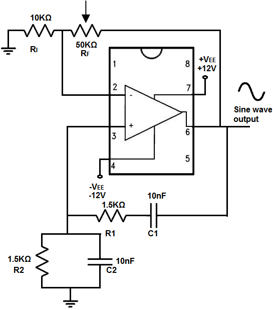
The connections are shown below.
Wien Bridge Oscillator Circuit Built with an LM741
The wien bridge oscillator circuit that we will build with an LM741 is shown below.
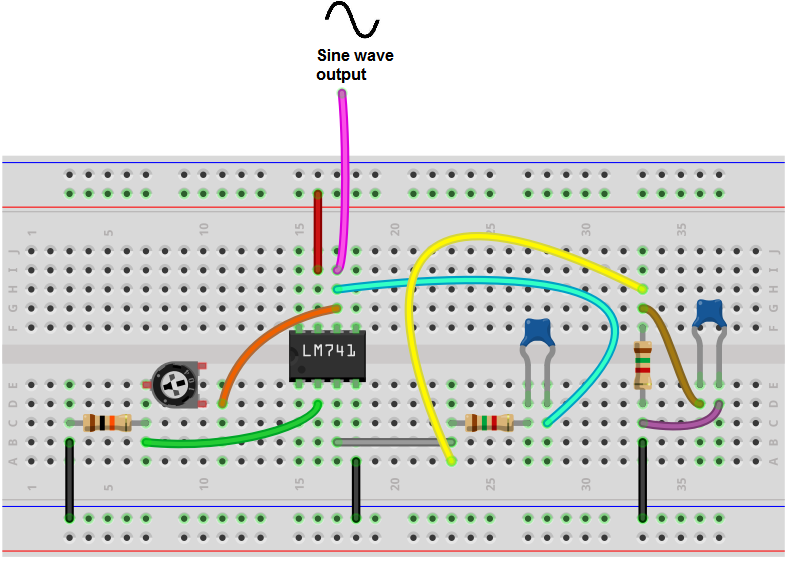
The breadboard circuit of the circuit above is shown below.
First and foremost, we use 12VDC of power for this circuit.
We connect +12V to +VEE,pin 7, and -12V to -VEE, pin 4. This establishes the power necessary for the LM741 chip.
So this circuit is made up of several different components, all of which are composed of either resistors, capacitors, or potentiometers.
So there are several formulas that we follow in order to get the frequency and gain that we desire for the circuit.
The frequency, f= 1/2πRC, where π= 3.14, r is equal to the resistance value, and C is equal to the capacitance values. These are for the R1, C1, R2, and C2 values.
The 2 RC network at the bottom of the circuit diagram determine the frequency of the output sine wave signal.
The 2 resistors should be of the same value and the 2 capacitors should be the same value.
For this circuit, we're going to create a frequency of 10KHz for the output signal.
To do this, we choose the values of 1.5KΩ for the resistor and 10nF for the capacitor. Doing the math, we get a frequency of, f= 1/2πRC= 1/2π(1.5KΩ)(10nF)= 1/2(3.14)(1500)(.00000001)≈ 10,615Hz. So, more or less, it is equal to 10KHz.
We can easily play around with values in order to change the frequency of the output signal.
If we swap out the 10nF capacitor for a 100nF capacitor, we get a frequency of f= 1/2(3.14)(1500)(.0000001)≈ 1061Hz, which is approximately 1KHz.
If we swap out the capacitor for a 1nF capaictor, we get a frequency of f= 1/2(3.14)(1500)(.000000001)≈ 106,157Hz, which is approximately 100KHz.
We can also do the same thing for the resistor. If we increase the value of the resistance, the frequency decreases. So if we increase the resistor from 1.5KΩ to 15KΩ while keeping the capacitor value unchanged, this will decrease the frequency by 10. If we change the resistor value to 150KΩ while keeping the capacitor value unchanged, this will decrease the frequency by 100.
So all these manipulations can be done in order to change the frequency.
Now we can focus on the gain, amplitude of the signal, which is how tall or loud the signal is.
The gain of the circuit is determined by the 2 top resistors, resistors RF and RI.
The gain of this circuit is determined by the formula, A= 1+ RF/RI, where RF= 2RI.
So since we are using a 10KΩ resistor for RI, the sweet spot for RF is about 20KΩ.
But being that this circuit is so precise and sensitive, it's better to have a potentiometer in place for adjustment than a fixed resistor. The potentiometer allows you to fine tune the resistance just right so that you can get a good sine wave signal at the output.
If the gain is too low, you will not get a sine wave at all for the output. If the gain is too high, the peaks of sine waves will be clipped and, thus, distorted. The potentiometer has to be adjusted so that there is an undistorted, unclipped sine wave as the output.
So to sum up this circuit, the op amp chip, in this case, an LM741 is used to create oscillations that are digital in nature, or square in nature.
The 2 RC networks on the bottom shape these digital waveforms into sine waves and they determine the frequency of the sine wave.
The RC networks form time constants in the circuit to determine how long one cycle is. The resistor-capacitor determines the time constant of the signal because they control the charge-discharge cycle time of the capacitor. The smaller the resistor and capacitor are, the shorter the time constant and, thus, the greater the frequency. This is because with less resistance, there is less impedement to the flow of current. Thus, a greater amount of current can flow more easily through the circuit. The smaller the capacitor, the less charge it can store, so it takes a shorter period of time for the capacitor to charge up. All this equates into a shorter time cycle for the capacitor, which means a greater frequency. Similarly, converse, if the resistor and capacitor value are greater, this creates a longer time constant and shorter frequency. With greater resistance, there is more impedement to the flow of current, so there is less current flow for a given period of time. With a greater capacitor value, the capacitor takes a longer time to charge up. And that's why a longer time cycle exists for the signal and, thus, a shorter frequency.
Apart from the RC networks, the 2 resistors, RF and RI determine the gain of the signal.
The output sine wave signals appears at pin 6 of the op amp, which is the output pin.
Keep in mind again that in order to get an output at pin 6, the potentiometer must be carefully tuned. This circuit is a very precise circuit. If the potentiometer isn't tuned precisely, there either will be no signal at the output or a clipped signal. You have to turn the potentiometer, so that it's just at the right resistance value. If not, you will either get no output or a clipped output that isn't sine wave like. If the resistance falls too low, you will not get no signal output at all. If the resistance goes too high, hte signal will be distorted and clipped. Thus, proper tuning is necessary.
So if you place the positive lead of the oscilloscope on this terminal and
the negative terminal on ground, you should see a sine wave if the potentiometer is adjusted
correctly.
And this is how a wien bridge oscillator can be built with an LM741 with
resistors, capacitors, and a potentiometer.
To see how this circuit operates in real life, see the video below.
Related Resources
How to Build a Triangle Wave Generator Circuit with an LM741 Op Amp
How to Build a Square-to-Triangle Wave Converter Circuit
How to Build a Square-to-Sine Wave Converter Circuit
How to Build a Clock Circuit with a 555 timer
How to Build an Astable Multivibrator Circuit with Transistors
How to Build a Multivibrator Circuit with a 4047 chip (for astable mode operation)
How to Build a Voltage-Controlled Oscillator Circuit with a 4046 Chip
How to Build an Oscillator Circuit with a 7414 Schmitt Trigger Inverter Chip
How to Build a Sine Wave Generator Circuit with a 555 Timer
How to Build a Ramp Generator with Transistors
How to Build a Voltage-controlled Oscillator with a 555 Timer Chip