How to Build an LC Tank Circuit Circuit
In this project, we will show how to build an LC tank circuit.
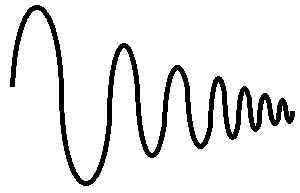
An LC tank circuit is a circuit that is composed of a single inductor and a single capacitor that creates a sinusoidal-like signal that begins with high voltage but then gradually decreases in amplitude as times goes on until it completely stops.
It's called a tank circuit because as time goes on, the energy in the circuit tanks, or dwindles till it's nonexistent.
It's basically a circuit that starts out very high energy but that loses its energy as time goes on.
How the LC tank circuit works is that an inductor and capacitors are in series with each other.
In order to charge up the circuit, we need a DC power source. The DC power source charges up the capacitor. Once the capacitor is charged up, now if we turn off or take away the DC power source, the capacitor discharges through the inductor. The current then goes across to charge the other terminal of the capacitor. Once fully charged, this capacitor discharges back to the 0V line. And this completes a full sinusoidal wave cycle. We explain this more in detail below.
We will also show how in this circuit you can adjust the amplitude of the frequency of the waveform.
Components Needed
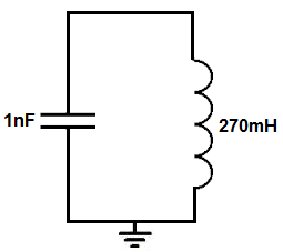
- 1nF ceramic capacitor
- 270mH inductor
The only 2 components that we need are a 1nF ceramic capacitor and a 270mH inductor.
the capacitor should be a ceramic capacitor, not an electrolytic, because charging needs to occur on both
sides of the capacitor. With an electrolytic capacitor, the leads are polarized, so it can only be charged on one side. With ceramic capacitors, the
leads are not polarized, so charging can occur on either terminals.
LC Tank Circuit
The LC tank circuit that we will build is shown below.
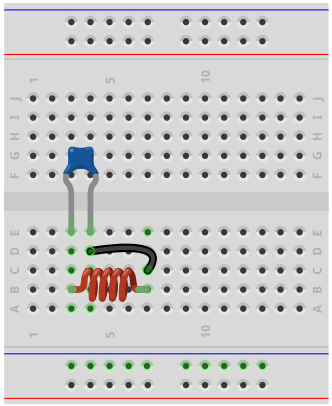
The breadboard circuit of the circuit above is shown below.
So in order for this circuit to work, it first must be charged by a DC power supply.
The power supply has to be DC because only DC can charge up a capacitor. At high-frequency (AC), the capacitor has a reactance (or resistance) according to the formula, XC= 1/2πfc. So according to the formula, the greater the frequency of the signal, the less reactance (or resistance) the capacitor offers. So at very high frequencies, signals travel unimpeded through the capacitor, almost as if it's not even there. So at these frequencies, capacitors do not store up charge. Only at low frequencies, such as DC, does the capacitor offer enough resistance that can only flow in one direction and is blocked in the other. This allows for DC current to charge up a capacitor.
So we connect a DC voltage source in parallel to the capacitor. While the DC source is on, the capacitor charges up. Once it's been on for a while, the capacitor will charge up to the voltage that is supplied to it. So if we feed the capacitor 9V, it will charge up to 9V.
Now, the action of our damped oscillation will occur when the power is removed from the circuit. Once we remove or turn off the DC power supply to the circuit, the capacitor will begin discharging. It discharges through the inductor.
The current then flows across the inductor and charges the other terminal of the capacitor.
The capacitor, once fully charged, then discharges again through the inductor and the whole process is repeated again.
To fully understand how this correlates to our sinusoidal signal, we will explain below.
When the capacitor is being charged up initially, this causes the positive ramp on the sinusoidal signal. As the capacitor is beginning charged, the voltage across it is increasing. When the voltage across the capacitor reaches the supply voltage connected to it, this is the peak of the sinusoidal waveform. When we remove the DC power supply and the capacitor begins to discharge, this begins the negative ramp of the DC signal. This is because the capacitor is losing voltage across it. When the capacitor is fully discharged, it has a voltage of 0V across, so this is when the voltage of the sinusodial waveform is 0V. Now, the current flows through the inductor and begins to charge up the other terminal of the capacitor. This is the part of the sinusoidal waveform that is increasing in negative voltage. As the capacitor continues to charge up, the negative voltage increases until it reaches its peak. Once it reaches the peak, the capacitor begins to discharge through the inductor again, and this the point in the sinusoidal waveform where the negative voltage goes from the negative voltage peak back to the 0V line. And this is how each of the steps of the LC tank circuit correlate to the sinusoidal waveform.
As the time progresses in the circuit, the peaks of the sine waveforms reach lower and lower amplitudes because of natural resistance that exists within the circuit and the fact that there is no constant power supply. So the circuit can really be seen as a temporary power source. So the voltage eventually dwindles until it's nonexistent.
So this is how the circuit works. Now we will talk about modifications that we can do to the circuit.
So there are 2 parameters of this circuit that we can modify. They are the frequency and amplitude of the signal.
First, with amplitude, we can vary the amplitude by changing the voltage of the DC power supply. The capacitor will charge to whatever voltage it is supplied, as long as it can tolerate that voltage level; this is the capacitor's voltage rating. As long as the voltage supplied is less than the capacitor's voltage rating, it will charge to that DC voltage. And this is how we can create a larger or smaller amplitude for the tank circuit.
Of course this amplitude won't last, because the amplitude progressively decreases as time goes on, but it really affects all the oscillations because the first waveform will be at the voltage level that the DC power supply is set to and each of the waveforms will be somewhat progressively smaller.
So amplitude is just a measure of the DC power supply level.
The next parameter we can adjust is the frequency of the sinusodal waveforms.
There will be a series of sine waves created by this circuit and we can adjust what frequency these signals will have by the selection of the inductor and capacitor value.
The frequency is determined by the formula, f= 1/2π√LC.
In our circuit, we have the frequency set to about 10KHz.
With a 270mH inductor and a 1nF capacitor, this equals a frequency of f= 1/2π√LC= 1/2π√(270mH)(1nF)= 9690Hz, which is approximately or near 10KHz.
If the frequency is desired to be about 1KHz, then a larger capacitor of 10nF is used along with the same 270mH inductor.
If the frequency is desired to be about 100Hz, then a larger capacitor of 100nF is used along with the same 270mH inductor.
If the frequency is desired to be about 10Hz, then a larger capacitor of 1μF is used along with the same 270mH inductor.
If the frequency is desired to be about 1Hz, then a larger capacitor of 10μF is used along with the same 270mH inductor. Since finding a 10μF ceramic capacitor may be difficult, you may need to use combine multiple capacitors in parallel to add up to the the 10μF capacitor value or somewhere near that value.
Decreasing the capacitor and inductor values increase the frequency, while increasing the capacitor and inductor values decrease the frequency.
This is because when the capacitor is a larger value, it takes a longer time to charge and discharge. This creates a longer time period for the signal, which results in a decreased frequency. The same true for an inductor's value. If the value is increased, the inductance has a stronger resistance to the flow of current. This creates a longer time signal, which creates a decreased frequency.
Vice versa, having a smaller capacitor increases frequency because the capacitor takes less time to charge and discharge. This creates a smaller time period and a larger frequency. With a smaller inductor, there is less resistance to the flow of current when the capacitor discharges and the time period is smaller, resulting in a greater frequency.
So this is how the circuit can be modified.
So if you take an oscilloscope and connect it in parallel to this circuit, you will see damped sinusoidal oscillations.
If you do not have an oscilloscope, you can visualize it with discrete components such as LEDs. Since the output waveform are sinusoidal waveforms that go from positive to negative
voltage, you can place one LED at output forward biased and the other LED reverse biased. You should see both LEDs turn on throughout the process to confirm that voltage in both directions is
occurring.
And this is how an LC tank circuit can be built.
The LC tank circuit is good for applications where you want AC power in both
directions for a short period of time.
Related Resources
How to Build a Square-to-Triangle Wave Converter Circuit
How to Build a Square-to-Sine Wave Converter Circuit
How to Build a Clock Circuit with a 555 timer
How to Build an Astable Multivibrator Circuit with Transistors
How to Build a Multivibrator Circuit with a 4047 chip (for astable mode operation)
How to Build a Voltage-Controlled Oscillator Circuit with a 4046 Chip
How to Build an Oscillator Circuit with a 7414 Schmitt Trigger Inverter Chip
How to Build a Sine Wave Generator Circuit with a 555 Timer
How to Build a Ramp Generator with Transistors
How to Build a Voltage-controlled Oscillator with a 555 Timer Chip