
How to Build a Sine Wave Generator Circuit with a Transistor

In this project, we will show how to build a sine wave generator with a single transistor and a few other components such as resistors and capacitors.
Before, we've shown how to build a sine wave generator with a 555 timer chip.
Now we'll show how to do this without a chip, simply by using discrete electronic components.
A sine wave generator is a circuit which can generate sine waves. This is the type of waveform that comes out of household electricity outlets. This is the waveform that you see in AC power.
Sine waves are also used a lot in acoustics. All different types of waveforms produce different sounds, so sine waves is one of many that are used in acoustics.
To build one, with this circuit, you don't even need a chip. Instead, all we need is a transistor and resistors and capacitors.
In this circuit, with the values listed, will build a sine wave generator that produces a frequency of about 1KHz.
However by varying the resistors or capacitors, the frequency can be modified to a higher or lesser level.
Components Needed
- 2N3904 NPN Transistor
- 4 1KΩ resistor
- 2KΩ resistor
- 1.8KΩ resistor
- 3 100nF ceramic capacitors
- 220nF ceramic capacitor
- 470nF ceramic capacitor
The 2N3904 transistor is an NPN transistor. The datasheet for this transistor can be found at the following link: 2N3904 NPN Transistor Datasheet.
You really could use any NPN transistor.
Apart from the transistors, all we need are resistors and ceramic capacitors.
Sine Wave Generator Circuit Built with a Transistor
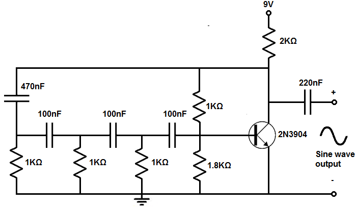
The sine wave generator circuit that we will build with a transistor and resistors and capacitors is
shown below.
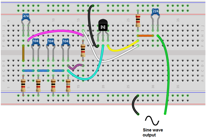
The breadboard circuit of the circuit above is shown below.
First and foremost, we use 9VDC of power for this circuit.
This circuit is composed of several subparts that make up the whole circuit. Each part serves its own purpose for the function.
The 1KΩ resistor in parallel with the 1.8KΩ resistor provide biasing to the 2N3904 transistor, bringing the transistor to its working point. If you create a much higher-frequency signal and the transistor doesn't work, these values may need to be modified.
Another component of the circuit is the frequency-dependent component. This part of the circuit determines the frequency of the sine wave. This part of the circuit is made up of the 3 1KΩ resistors and the 3 100nF ceramic capacitors. These 6 components- 3 100nF ceramic capacitors and 3 1KΩ resistors- determine the frequency of the output sine waveform.
If you want to modify the frequency of the sine wave, then you would change these components. These components form RC networks. The time constant of the signal, τ= RC. So if you want the signal to have a longer time period, then you would either increase the resistance or increase the capacitance. This decreases the frequency. If you want the signal to have a shorter time period, then you would either decrease the resistance or decrease the capaictance. Since the signal has a shorter time period, it has a greater frequency.
With these circuit, it is recommended that you change all 3 capacitance values at once or all 3 resistance values at once.
With the values as shown above, the frequency is just about at 1KHz.
If you wanted to increase the frequency, then you could just change all 3 100nF capacitors to 10nF capacitors. If you want to increase the frequency more, you could change the capacitors to 1nF. You can also change the resistors values to a lower value, such as 500Ω. You can just play around with the values and see how the frequency changes in response.
The 470nF capacitor is a capacitor that takes the sine wave output signal and feeds it back into the input. This keeps the oscillations going so that continuous oscillations occur.
The 220nF capacitor acts as a coupling capacitor. It passes the AC signal through to output but blocks the DC signal which is needed for power. Therefore, it doesn't create DC offset with the AC signal.
And this is how a sine wave generator circuit can be built with a few simple components.
To see how this circuit works in real life, see the video below.
Related Resources
How to Build a Square-to-Triangle Wave Converter Circuit
How to Build a Square-to-Sine Wave Converter Circuit
How to Build a Triangle Wave Generator Circuit with a 555 Timer
How to Build a Clock Circuit with a 555 timer
How to Build an Astable Multivibrator Circuit with Transistors
How to Build a Multivibrator Circuit with a 4047 chip (for astable mode operation)
How to Build a Voltage-Controlled Oscillator Circuit with a 4046 Chip
How to Build an Oscillator Circuit with a 7414 Schmitt Trigger Inverter Chip
How to Build a Ramp Generator with Transistors
How to Build a Voltage-controlled Oscillator with a 555 Timer Chip