
How to Build a Power Inverter Circuit
In this project, we will show how to build a power inverter circuit.
A power inverter circuit is a circuit that converts DC power to AC power.
You can make the AC power be any level that you want and to any frequency that you want.
The popular values to boost the AC voltage level to is either 110-120V or 220-140V because these are the AC voltages that are used worldwide.
In the United States, we use either 120/240V, with 120V being much more common. Therefore, for this circuit, we will have an output AC voltage of 120V.
We accomplish this voltage, we use a transformer with a 1:10 amplification. So if we are able to use a 12V battery to power our circuit, when we submit to to the input of the power transformer, it will turn that 12VDC into 120VAC.
So in order to do this circuit, we will need a 120VAC power supply transformer that takes an input of 12V.
How we accomplish the frequency of the circuit is through a resistor-capacitor (RC) network. By carefully choosing the values of the resistor and capacitors, we can have a signal that has a frequency in the desired range we want it.
In the United States, the standard frequency is 60Hz for AC voltage from wall outlets. Therefore, we will try to mimic this frequency as close as possible. Later on, we can test the frequency with either a multimeter, oscilloscope, or frequency counter to ensure its accuracy. Worldwide, frequencies are either 50Hz or 60Hz, so there is not much variation. So with a slight tweak of values, we can have either frequency, if you desire the frequency where you are living.
By doing this circuit and getting the AC voltage amplitude and frequency that our country we live in uses, we are imitating the function of an AC wall outlet. Therefore, devices that are powered by connecting to a wall outlet can now be powered directly by our inverter circuit. This is one of the chief reasons inverters are used. So if power were to go out for any reason, we could still power on a device that connects to AC power in the event of an emergency. This is why a lot of people have spare inverters lying around. It totally replaces the function of a wall outlet, assuming one simple condition- that the inverter has enough power to turn on that object.
If you're dealing with a 1000W inverter, and the device you're power needs 1500W such as a typical heater running in high power, the inverter circuit won't be able to do it. You have to know that power limitations of the said inverter. This is why if you look at commercial inverters, they will have specifications to the amount of power they can output. Power is a function of voltage vs current. So if the inverter puts out 120 volts and can output up to 12A of current, it has a power rating of 1440 watts.
The maximum watts our circuit can deal with will be a function of the power transformer used. You have to check your power transformer for the maximum current it can output. This multiplied by the output voltage will be the maximum wattage for the circuit.
We'll show in detail how to build this circuit below.
Components Needed
- 12V Battery
- Power Transformer 120VAC Primary 12VAC Secondary
- 2 2N2222 BJT transistors
- 2 IRF640 Power MOSFETs
- 2 16.5KΩ resistors
- 2 680Ω resistors
- 2 1µF capacitor
The type of battery we will use for this circuit is one of those big 12V batteries, such one you would find in a car. These types of batteries give out 12V with several amperes of current output capability, typically about 7A of current. This allows for large output powering. This is not a small battery such as a 'AA' battery.
An power inverter is really a powerful backup power supply used frequently in the event of AC mains power goes down. Therefore, it uses heavy duty backup power.
In case you just want to test the circuit without actually connecting all the true components, you can use a DC power supply switched to 12V with current capability turned on to replicate the effect of a 12V battery.
Apart from the battery, we need a power transformer. Since we are using a 12V battery to supply our voltage, we need a power transformer that converts from 12VAC to 120VAC. But you don't have to choose this voltage. You may want another voltage. In that case, just make sure it can use the 12VAC to convert it into the voltage you want, whether that's 110VAC or 220VAC or 230VAC or 240VAC. This may be the voltage that your device operates on. For this circuit, you can use any output AC voltage, without it affecting any other part of the circuit.
Then we just need a few transistors, and resistors and capacitors.
We use the IRF640 power MOSFETs because they are able to withstand high powers such as those used in this circuit and they provide voltage amplification so the circuit gets a power boost.
The IRF6400 is an N-channel power MOSFET that can handle up to 200V and 18A of continuous drain current.
The datasheet for the IRF640 is shown at the following link: IRF640 MOSFET transistor datasheet.
The whole part of the circuit composed of the 2N2222 transistors with the resistors and capacitors is a multivibrator circuit. The 2 2N2222 NPN transistors really act as switches in this circuit so that this part of the circuit can have a multivibrator effect, which creates square waveforms.
The values of the resistors and capacitors form an RC network that
determines the frequency of the circuit. The values that we chose output a frequency
of 60Hz.
Power Inverter Circuit
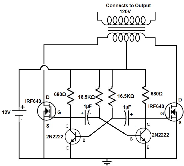
The power inverter circuit that we will build with a power transformer along with a few simple components is shown below.
The breadboard circuit of the circuit above is shown below.

The first thing is powering the circuit. You can use a variety of voltages to power the circuit. It depends on the type of transformer you have and the voltage you want output. If you have a transformer with a 1:10 turns ratio and you want 120V, then 12V is what you should use, since 12V * 10= 120V. If you are using a transformer with a 1:20 ratio and 120V as output, then 6V is the voltage to use. Usually, however, you want to use a multiple of 12, because the large batteries that provide very good power, are 12V batteries. Therefore, if you are using voltage to power the inverter circuit, you want to use 12V or 24V ideally. The 12V would be a single battery, while the 24V would be 2 batteries in series, yielding 24V. So using a different voltage won't fundamentally change the circuit or not make it work, so you can modify this.
Now the circuit composed of the 2 2N2222 NPN transistors, the 2 1µF electrolytic capacitors, the 2 680Ω resistors, and the 16.5KΩ resistors form a multivibrator circuit that determines the frequency of the output. It's really the 1µF capacitors and the 16.5KΩ resistors that chiefly determine the frequency. Since the resistor and capacitor pair form an RC network, the time constant that the output switches on and off at is determined by the formula, =RC= (16.5KΩ)(1µF)= 0.0165s. The inverse of the time constant is the frequency, f=1/τ= 1/0.0165s ≈ 60Hz.
It may be hard to obtain 16.5KΩ resistors, so just use resistor values that are close to this value.
This part of the circuit is a multivibrator. It creates the square waveforms. When one transistor is on, the other is off. This allows for positive and negative cycles. The capacitor charging and discharging in cycles produces this type of signal in the RC network.
The MOSFET transistors are power transistors. They provide amplification to the signal created from the multivibrator circuit. Since the MOSFETs are power transistors, they can withstand a lot of power. If you are using the same MOSFETs in this circuit, make sure that the ones you are using are power MOSFETs, especially if you are using a lot of voltage to power this circuit.
So now we're at the last part of this circuit- connecting it to the transformer. So the transformer is a device made up of 2 coils. There is a primary coil and a secondary coil. We connect the output of this circuit to the primary coil. This induces a voltage in the secondary in proportion to the turns ratio of the transformer. If you are using a transformer with a 1:10 turns ratio, the output voltage will be 10 times the value of the input voltage.
It may be difficult to find a step up transformer that has a 1:10 turns ratio. So a step-down transformer can be used in place. With a step-down transformer, however, instead of connecting the multivibrator circuit to the primary coil, we connect it to the secondary coil. Then we connect the output of the transformer to the primary coil. This is if we cannot find a step-up transformer. Just make sure not to exceed the limits of the primary and secondary coils. For example, if using a 120V primary coil and a 24V secondary coil, do not exceed the 24V on the secondary coil. This is the maximum rating, so it should not be exceeded.
If you want to be able to power on and off the inverter without having to disconnect the battery or DC power supply, a switch can be added right above the positive voltage of the DC power source. So if you want to turn off the inverter without having to disconnect the battery every time, you simply open the switch, allowing no power to the circuit.
And this is how a power inverter circuit can be built can be built with a power
transformer and a few resistors and capacitors.
Important note- Please note that an earlier version of this article stated that this circuit produces a sinusoidal signal as its output. This has now been corrected. This circuit is a square wave generator and does not output sine waves as its output. This circuit is also a very basic entry-level power inverter circuit that does not have any overvoltage protection, overcurrent protection (such as using a fuse), or any safety mechanisms in place. As it is, this is circuit should only be used for a basic, entry-level, educational-only purpose. It is not production ready and really should not be used on real-life products or any valuable electronics. Only cheap, disposable electronic products should be used for testing as you deem fit. Again, there is no protection against voltage spikes and all the protection needed for a power electronics device. This is just a basic power inverter that would need more advanced circuitry to be used to protect real-world devices. This website takes no responsibility for any damage or even fires that could result from the building of this circuit.
Advanced power inverters feature cooling systems such as the use of a fan, temperature monitoring, LCD displays to show the power output, alarm systems such as if there is overheating, etc. Obviously these go beyond the scope of a basic begineer power inverter circuit and would be overkill for a beginner. This circuit is meant to be a first step to creating an advanced power inverter.
Related Resources
How to Build a Square-to-Triangle Wave Converter Circuit
How to Build a Square-to-Sine Wave Converter Circuit
How to Build a Clock Circuit with a 555 timer
How to Build an Astable Multivibrator Circuit with Transistors
How to Build a Multivibrator Circuit with a 4047 chip (for astable mode operation)
How to Build a Voltage-Controlled Oscillator Circuit with a 4046 Chip
How to Build an Oscillator Circuit with a 7414 Schmitt Trigger Inverter Chip
How to Build a Sine Wave Generator Circuit with a 555 Timer
How to Build a Ramp Generator with Transistors
How to Build a Voltage-controlled Oscillator with a 555 Timer Chip