How to Build a TMP36 Temperature Sensor Circuit
In this project, we will demonstrate how to build temperature sensor circuit using a TMP36 sensor.
As a temperature sensor, the circuit will read the temperature of the surrounding environment and relay the temperature to us back in degrees fahrenheit.
The IC we will use to measure the temperature is the TMP36 IC. We will integrate this with the arduino to
measure the temperature. The arduino will then read this measured value from the TMP36 and translate into degrees
fahrenheit and celsius,
which we will be able to read from the computer from the arduino serial monitor.
Components Needed to Build the TMP36 Temperature Sensor Circuit
- Arduino Board
- TMP36 Temperature Sensor IC
- Computer
- USB with type A and B connectors
We can use any type of arduino board.
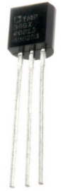
The TMP36 is a low voltage IC which uses between 2.7V and 5.5V of power. This is ideal because the arduino's power pin gives out 5V of power. The IC has just 3 pins, 2 for the power supply and one for the analog output. The output pin provides a voltage output that is linearly proportional to the celsius (centigrade) temperature. In order to get the temperature in fahrenheit, we have to write code to the arduino to convert this celsius temperature into fahrenheit. The code is shown below.
Below is the pinout of the TMP36 IC:
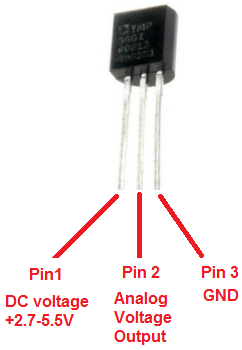
Pin 1 receives positive DC voltage in order for the IC to work. This, again, is voltage between 2.7-5.5V. Pin 3 is the ground, so it receives the ground or negative terminal of the DC power supply. And Pin 2 is the output of the IC, outputting an analog voltage in porportion to the temperature it measures.
This is the datasheet of the TMP36 IC: TMP36 Temperature Sensor IC Datasheet.
The arduino, with suitable code, can then interpret this measured analog voltage and output to us the temperature in degrees fahrenheit.
Also to do this project we need a USB cable with a Type A connector on one end and a Type B connector
on the other end. This is so that we can hook our arduino to a computer and send it code that it can run to dispaly
to us the temperature.
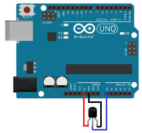
Temperature Sensor Circuit Schematic
The temperature sensor circuit we will build is shown below:
This translates into the circuit schematic:
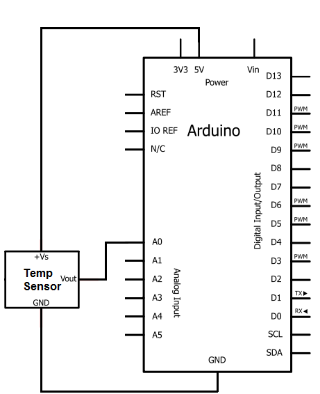
So you circuit connections are:
Pin 1 of the TMP36 goes into +5V of the arduino
Pin 2 of the TMP36 goes into analog pin A0 of the arduino
Pin 3 of the TMP36 goes into ground (GND) of the arduino
Now that we have this circuit setup, we now connect the USB cable from the arduino to the computer.
The type B side of the connector goes into the arduino and the type A side into the USB port of the computer.
Now the computer is connected to the arduino. We can now write code in the processing software to give instructions to the
arduino.
Code for Temperature Sensor Circuit
int outputpin= 0;
void setup()
{
Serial.begin(9600);
}
void loop()
{
int rawvoltage= analogRead(outputpin);
float volts= rawvoltage/205.0;
float celsiustemp= 100.0 * volts - 50;
float fahrenheittemp= celsiustemp * 9.0/5.0 + 32.0;
Serial.print(celsiustemp);
Serial.println(" Celsius");
Serial.print(fahrenheittemp);
Serial.println(" Fahrenheit");
delay(300000);
}
The code will now be explained. Before we can get a celsius or fahrenheit reading of the temperature, the analog output voltage must first be calculated. This will be the raw value (between 0 and 1023) divided by 205. It is divided by 205 because a span of 1024 values occupies 5V, or 1024/5= 205 per volt.
Once this the analog voltage is calculated, we can find the degrees in celsius by the equation: celiustemp= 100.0 * volts -50
We then can find the temperature in fahrenheit by the equation: fahrenheittemp= celiustemp * 9.0/5.0 + 32.0
At the end of this program, we put a delay of 5000ms to take the temperature reading every 5 seconds. You can adjust this value to meet your personal preference or program needs.
To see this circuit in action, watch the following video below.
To see how to integrate this circuit to an LCD for an LCD readout instead of from the Serial Monitor, see
How to Integrate a Temperature Sensor Circuit to an LCD.
Related Resources
How to build a LM35 Temperature Sensor Circuit
How to build a LM34 Temperature Sensor Circuit
How to build a LM335 Temperature Sensor Circuit
How to Build a Hall Effect Sensor Circuit
How to Build a Laser Diode Circuit
How to Build a Relay Driver Circuit
How to Build an Overvoltage Protection Circuit
How to Build a Transient Voltage Suppressor (TVS) Circuit
How to Build a Touch Sensor Circuit
How to Build an Accelerometer Circuit
How to Build a Motion Detector Circuit
How to Build a Vibration Detector Circuit